Direct answer: the rod seal is usually not the first component to fail
If a hydraulic cylinder leaks again shortly after a rod seal replacement, assigning the failure to compound or hardness will usually miss the real source. The rod seal operates inside a boundary made of bore, rod, guide, groove, wiper, lubricating film and external environment. It is the easiest component to replace and the easiest one to blame.
The first questions are evidence questions: where does the leak start, how did the used part fail, is the rod surface damaged, does the extrusion gap open under pressure, how does contamination enter, is there side load or eccentric wear, and was the lip cut during installation? Material upgrades only matter after these variables are understood.
- Read the failure form before changing material
- Measure pressure peaks, not only nominal system pressure
- Inspect rod surface and guide clearance before the groove
- Control contamination and installation before claiming a life upgrade
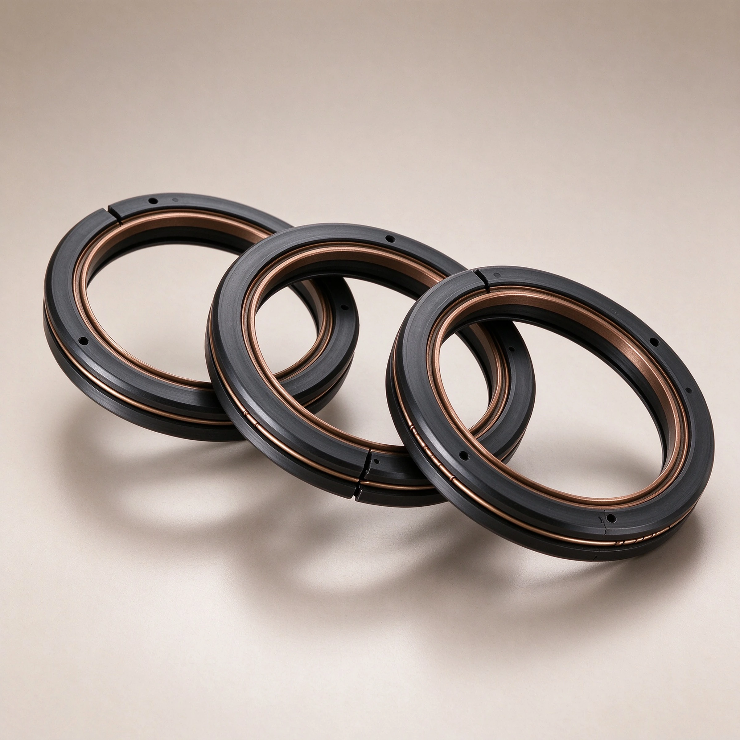
A rod seal is a dynamic boundary, not a standalone part
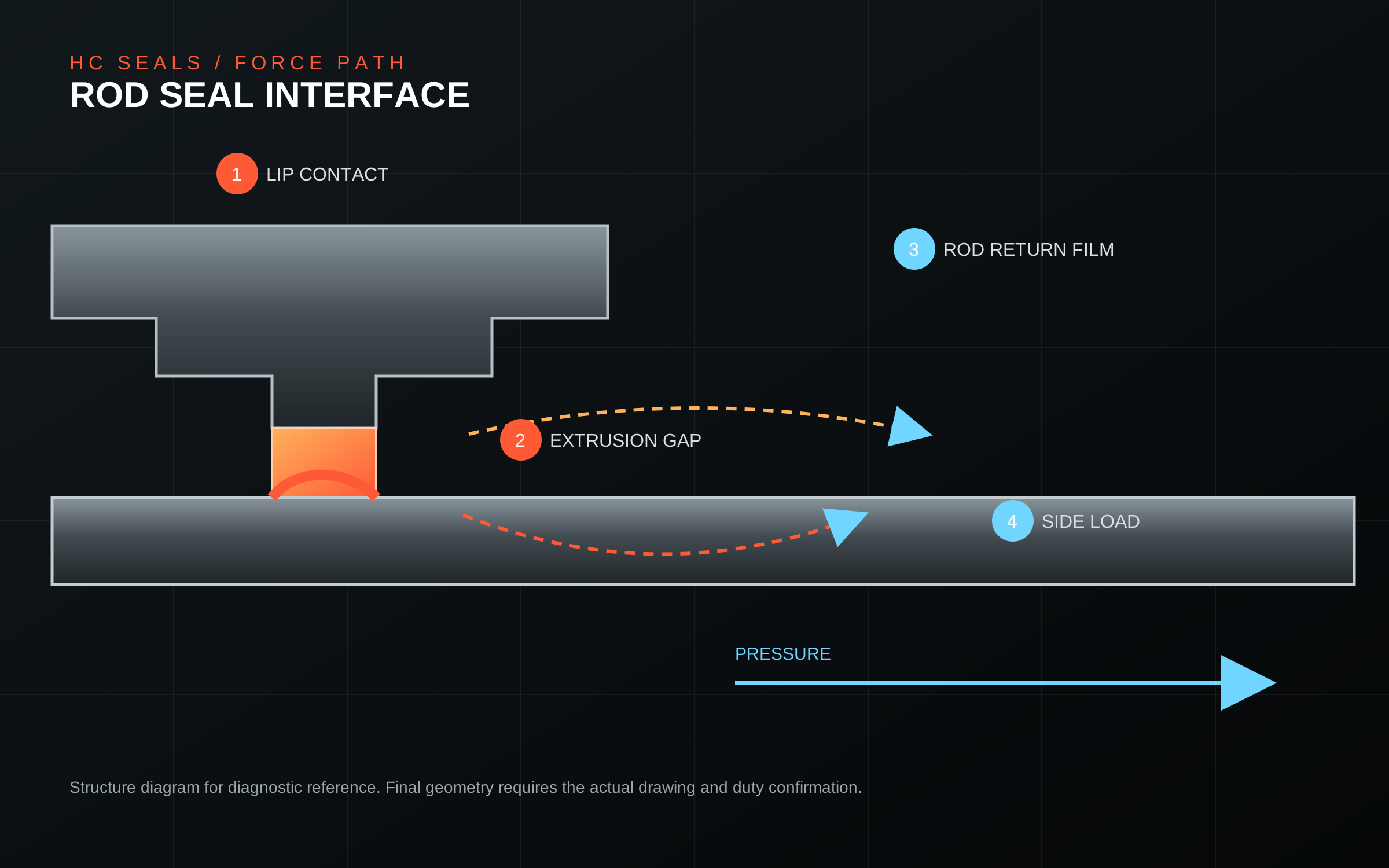
During reciprocation, the lip must keep enough contact stress to stop oil from crossing the interface, while keeping friction low enough to preserve the lubricating film. The balance must survive low pressure, pressure peaks, direction changes, dwell, side load and temperature change.
At least four interfaces matter: lip-to-rod, seal OD-to-groove, wiper-to-environment and guide-to-rod. Failure at any interface can appear as a rod-end leak.
- Lip and rod: oil-film thickness, return flow and friction heat
- OD and groove: static sealing and axial load
- Wiper and environment: particles, water and cleaning fluid
- Guide and rod: side load, eccentricity and contact pressure
Read the used part: six failure forms point to six different variables
A report that only says the seal is damaged has no diagnostic value. Record whether wear is uniform, whether the rod has longitudinal scoring, whether the compound is hard or swollen, whether the root is extruded, whether the wiper contains mud or metal particles, and whether the OD shows a bright band or flattening.
| Failure form | Typical evidence | First variables to inspect |
|---|---|---|
| Cut or torn lip | Local cut; leak immediately after assembly | Sleeve, thread, keyway, burr and direction |
| Skewed lip wear | One-sided wear or uneven contact band | Side load, guide wear, alignment and bent rod |
| Root extrusion | Flattened root or material pushed into gap | Pressure peaks, groove gap, support ring and temperature |
| Hardening or cracking | Loss of elasticity and surface cracks | Temperature peaks, media and aging |
| Swelling or softening | Dimension growth and low hardness | Media composition, cleaner, mixed oil and contamination |
| Rod scoring | Longitudinal grooves or coating loss | Wiper failure, hard particles, coating and external dust |
Pressure peaks and extrusion gap matter more than a pressure rating
A system may have a moderate nominal pressure while valve closure, load reversal and oil compression create short pressure peaks far above the gauge average. The seal is pushed toward one side of the groove. If the material and support structure cannot resist the actual gap, the root extrudes.
Do not rely on a catalogue pressure number. Record pressure waveform, peak duration, pressure rise rate, actual groove gap, thermal growth and support structure. The effective gap is the result of machining, assembly and operating load, not a nominal drawing value.
- Measure peak pressure, rise rate and hold time
- Check groove diameter, width, radius and opening gap
- Inspect the seal root for bright bands, flattening or shear
- Confirm support-ring material and position
Material follows media and temperature, not habit
NBR covers many hydraulic oils but has limits in heat, ozone and polar media. FKM extends heat and chemical resistance but is not universal. PU offers wear and extrusion resistance but can be sensitive to hydrolysis and temperature. PTFE provides low friction and chemical resistance but needs preload and anti-extrusion design.
The material decision must include media composition, continuous and peak temperature, cleaning agents, mixed-oil history, pressure cycles, hardness and compression set. A material abbreviation is not a validated compound.
- Provide fluid grade, composition, contamination and cleaners
- Separate continuous, start-up and peak temperatures
- Define hardness, compression set and rebound targets
- Use food, pharma or drinking-water claims only with real documents
Rod surface is more than one roughness number
The lip depends on a stable oil film. Longitudinal texture, spiral marks, coating loss, impact damage or a local roughness change can create uneven shear on every stroke. Blind polishing can change film formation and lip contact rather than improve it.
Inspect roughness, texture direction, coating integrity and local damage together. Longitudinal scoring often points to external particles; circumferential marks may point to turning or grinding.
- Record roughness and texture direction
- Check coating loss, impact marks, corrosion and longitudinal grooves
- Confirm straightness, roundness and end chamfer
- Avoid local polishing that destroys the global oil film
The wiper cannot carry the whole contamination problem
Dust and particles enter through the wiper, form an abrasive band on the rod and then reach the rod seal. A new rod seal without a wiper and cleaning improvement will repeat the failure.
Contamination control covers external dust, assembly particles, oil particles and maintenance practice. The space between wiper and rod seal must not become a particle reservoir.
- Identify dust, mud, cleaning fluid and particle hardness
- Check wiper lip direction and return path
- Control assembly environment, tools and cleaning fluid
- Prevent particles from being pressed into the seal during service
Side load turns uniform lip pressure into skew wear
Side load, misalignment or guide wear makes the rod move eccentrically. One side of the lip then carries higher pressure and the other side lower pressure. A leak path forms, and increasing hardness may accelerate the skew wear.
Measure guide clearance, rod straightness, alignment and structural deflection under real load. Rod seal and guide belong to the same motion interface.
- Measure guide clearance, straightness and alignment
- Record side-load direction and wear position
- Evaluate thermal growth and structural deflection
- Redesign guidance when needed instead of increasing seal hardness
Installation damage invalidates the design calculation
A thin lip can be cut by threads, keyways, chamfers, burrs or steps. Dry assembly, wrong lubricant, uncontrolled compression, eccentric tooling or excessive insertion speed can create initial damage that grows into a leak.
Use a proper sleeve, protection cap, compatible lubricant, clean station and clear orientation. Record tooling, lubricant, insertion direction and operator.
- Cover threads, keyways and sharp edges
- Use dedicated sleeve and protection cap
- No dry installation and no unknown lubricant
- Record tooling, orientation and lubricant
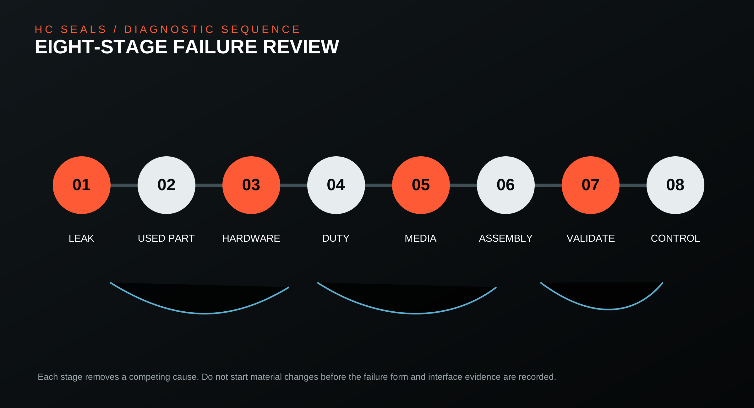
An eight-step diagnostic sequence
A reliable diagnosis must build an evidence chain instead of relying on experience alone. Separate leakage path, used-part form, hardware condition, duty and installation records.
- Confirm leak location and stage: start-up, hold, reversal, full load or after stop
- Inspect lip, root, OD and wiper and photograph each failure form
- Measure rod surface, groove, clearance, guide wear and alignment
- Collect pressure waveform, temperature, speed, stroke and media
- Check oil particles, external dust, cleaners and mixed-oil history
- Review installation tooling, lubricant, direction and compression
- Validate pressure, temperature, life and leakage under the same duty
- Rebuild material, structure, surface or system control from the evidence
A seal that does not leak on installation is not yet validated
Validation must cover low-pressure start, peak pressure, hold, reversal shock, thermal cycling, side load and contamination. A static hold test does not reveal lip return, friction heat or long-term wear.
Tie the result to a specific revision. Any change to compound, groove, rod surface, lubricant or tooling requires a new review.
- Record pressure profile, temperature and cycle count
- Measure leakage, friction, temperature rise and rod change
- Inspect lip contact band, root extrusion and material aging
- Keep failed samples and their duty data
Can a high-temperature compound stop rod-seal leakage?
Only if temperature or media is the confirmed cause. If the interface has extrusion, rod damage, side load or particles, a new compound changes the failure time but not the failure source.
Does higher hardness reduce extrusion?
Hardness changes resistance to deformation. It does not replace correct clearance, support rings and pressure control. Excessive hardness may increase friction and skew wear.
Is a smoother rod always better?
No. The lip needs a stable oil film and suitable texture. Blind polishing can change film formation and requires validation with the actual compound and speed.
Why does an imported seal still leak?
An imported compound cannot repair the interface. Groove dimensions, rod surface, guide clearance, contamination, installation damage and pressure peaks remain active.
How can extrusion and installation cuts be distinguished?
An installation cut is usually a local lip edge cut or tear. Extrusion often appears as a flattened root, bright band or material pushed into the gap. Final confirmation requires groove gap, pressure waveform and assembly records.
What to send for a useful failure review
A photo of a seal is not enough. Provide the duty, hardware dimensions, media, failure form and validation target so the supplier can build a failure tree and selection route instead of offering an existing part number.
- Equipment type, rod diameter, stroke, speed and cycle rate
- Nominal pressure, peak pressure, waveform and hold time
- Ambient, media, start-up and cleaning temperatures
- Media, contamination, mixed-oil history, cleaner and external dust
- Groove drawing, rod surface, guide clearance and alignment
- Used-part photos, leak location, service time and replacement history
- Target life, allowable leakage, envelope and current problem